|
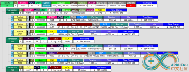
这次的目标是实现一个 USB 转串口的设备,参考的是Arduino Leonardo 的 USB CDC。这个串口是标准USB串口,在Windows下无需驱动。首先抓取描述符如下: USB Composite Device | Connection Status | Device connected | | Current Configuration | 1 | | Speed | Full (12 Mbit/s) | | Device Address | 4 | | Number Of Open Pipes | 3 |
Device Descriptor ArduinoLeonardo | Offset | Field | Size | Value | Description | | 0 | bLength | 1 | 12h | | | 1 | bDescriptorType | 1 | 01h | Device | | 2 | bcdUSB | 2 | 0200h | USB Spec 2.0 | | 4 | bDeviceClass | 1 | EFh | Miscellaneous | | 5 | bDeviceSubClass | 1 | 02h | Common Class | | 6 | bDeviceProtocol | 1 | 01h | Interface Association Descriptor | | 7 | bMaxPacketSize0 | 1 | 40h | 64 bytes | | 8 | idVendor | 2 | 2341h | | | 10 | idProduct | 2 | 8036h | | | 12 | bcdDevice | 2 | 0100h | 1.00 | | 14 | iManufacturer | 1 | 01h | "Arduino LLC" | | 15 | iProduct | 1 | 02h | "Arduino Leonardo" | | 16 | iSerialNumber | 1 | 03h | | | 17 | bNumConfigurations | 1 | 01h | |
Configuration Descriptor1 Bus Powered, 500 mA | Offset | Field | Size | Value | Description | | 0 | bLength | 1 | 09h | | | 1 | bDescriptorType | 1 | 02h | Configuration | | 2 | wTotalLength | 2 | 004Bh | | | 4 | bNumInterfaces | 1 | 02h | | | 5 | bConfigurationValue | 1 | 01h | | | 6 | iConfiguration | 1 | 00h | | | 7 | bmAttributes | 1 | A0h | Bus Powered, Remote Wakeup | | 4..0: Reserved | | ...00000 | | | 5: Remote Wakeup | | ..1..... | Yes | | 6: Self Powered | | .0...... | No, Bus Powered | | 7: Reserved (set to one)
(bus-powered for 1.0) | | 1....... | | | 8 | bMaxPower | 1 | FAh | 500 mA |
Interface AssociationDescriptor Abstract Control Model | Offset | Field | Size | Value | Description | | 0 | bLength | 1 | 08h | | | 1 | bDescriptorType | 1 | 0Bh | Interface Association | | 2 | bFirstInterface | 1 | 00h | | | 3 | bInterfaceCount | 1 | 02h | | | 4 | bFunctionClass | 1 | 02h | CDC Control | | 5 | bFunctionSubClass | 1 | 02h | Abstract Control Model | | 6 | bFunctionProtocol | 1 | 00h | | | 7 | iFunction | 1 | 00h | |
Interface Descriptor 0/0 CDCControl, 1 Endpoint | Offset | Field | Size | Value | Description | | 0 | bLength | 1 | 09h | | | 1 | bDescriptorType | 1 | 04h | Interface | | 2 | bInterfaceNumber | 1 | 00h | | | 3 | bAlternateSetting | 1 | 00h | | | 4 | bNumEndpoints | 1 | 01h | | | 5 | bInterfaceClass | 1 | 02h | CDC Control | | 6 | bInterfaceSubClass | 1 | 02h | Abstract Control Model | | 7 | bInterfaceProtocol | 1 | 00h | | | 8 | iInterface | 1 | 00h | |
Header FunctionalDescriptor | Offset | Field | Size | Value | Description | | 0 | bFunctionLength | 1 | 05h | | | 1 | bDescriptorType | 1 | 24h | CS Interface | | 2 | bDescriptorSubtype | 1 | 00h | Header | | 3 | bcdCDC | 2 | 0110h | 1.10 |
Call ManagementFunctional Descriptor | Offset | Field | Size | Value | Description | | 0 | bFunctionLength | 1 | 05h | | | 1 | bDescriptorType | 1 | 24h | CS Interface | | 2 | bDescriptorSubtype | 1 | 01h | Call Management | | 3 | bmCapabilities | 1 | 01h | | | 7..2: Reserved | | 000000.. | | | 1: Data Ifc Usage | | ......0. | Call management only over Comm Ifc | | 0: Call Management | | .......1 | Handles call management itself | | 4 | bDataInterface | 1 | 01h | |
Abstract ControlManagement Functional Descriptor | Offset | Field | Size | Value | Description | | 0 | bFunctionLength | 1 | 04h | | | 1 | bDescriptorType | 1 | 24h | CS Interface | | 2 | bDescriptorSubtype | 1 | 02h | Abstract Control Management | | 3 | bmCapabilities | 1 | 06h | | | 7..4: Reserved | | 0000.... | | | 3: Connection | | ....0... | | | 2: Send Break | | .....1.. | Send Break request supported | | 1: Line Coding | | ......1. | Line Coding requests and Serial State notification supported | | 0: Comm Features | | .......0 | |
Union FunctionalDescriptor | Offset | Field | Size | Value | Description | | 0 | bFunctionLength | 1 | 05h | | | 1 | bDescriptorType | 1 | 24h | CS Interface | | 2 | bDescriptorSubtype | 1 | 06h | Union | | 3 | bControlInterface | 1 | 00h | | | 4 | bSubordinateInterface0 | 1 | 01h | CDC Data |
Endpoint Descriptor 81 1In, Interrupt, 64 ms | Offset | Field | Size | Value | Description | | 0 | bLength | 1 | 07h | | | 1 | bDescriptorType | 1 | 05h | Endpoint | | 2 | bEndpointAddress | 1 | 81h | 1 In | | 3 | bmAttributes | 1 | 03h | Interrupt | | 1..0: Transfer Type | | ......11 | Interrupt | | 7..2: Reserved | | 000000.. | | | 4 | wMaxPacketSize | 2 | 0010h | 16 bytes | | 6 | bInterval | 1 | 40h | 64 ms |
Interface Descriptor 1/0 CDCData, 2 Endpoints | Offset | Field | Size | Value | Description | | 0 | bLength | 1 | 09h | | | 1 | bDescriptorType | 1 | 04h | Interface | | 2 | bInterfaceNumber | 1 | 01h | | | 3 | bAlternateSetting | 1 | 00h | | | 4 | bNumEndpoints | 1 | 02h | | | 5 | bInterfaceClass | 1 | 0Ah | CDC Data | | 6 | bInterfaceSubClass | 1 | 00h | | | 7 | bInterfaceProtocol | 1 | 00h | | | 8 | iInterface | 1 | 00h | |
Endpoint Descriptor 02 2Out, Bulk, 64 bytes | Offset | Field | Size | Value | Description | | 0 | bLength | 1 | 07h | | | 1 | bDescriptorType | 1 | 05h | Endpoint | | 2 | bEndpointAddress | 1 | 02h | 2 Out | | 3 | bmAttributes | 1 | 02h | Bulk | | 1..0: Transfer Type | | ......10 | Bulk | | 7..2: Reserved | | 000000.. | | | 4 | wMaxPacketSize | 2 | 0040h | 64 bytes | | 6 | bInterval | 1 | 00h | |
Endpoint Descriptor 83 3In, Bulk, 64 bytes | Offset | Field | Size | Value | Description | | 0 | bLength | 1 | 07h | | | 1 | bDescriptorType | 1 | 05h | Endpoint | | 2 | bEndpointAddress | 1 | 83h | 3 In | | 3 | bmAttributes | 1 | 02h | Bulk | | 1..0: Transfer Type | | ......10 | Bulk | | 7..2: Reserved | | 000000.. | | | 4 | wMaxPacketSize | 2 | 0040h | 64 bytes | | 6 | bInterval | 1 | 00h | |
实现了上面的描述符之后,就能保证插入系统后 Windows 设备管理器上不会出现惊叹号。Windows支持的标准 CDC 动作有下面8个【参考1】 1. SET_LINE_CODING 用于主机对设备设置波特率,停止位,奇偶校验和位数 2. GET_LINE_CODING用于主机取得设备当前波特率,停止位,奇偶校验和位数 3. SET_CONTROL_LINE_STATE 用于产生 RS-232/V.24标准的控制信号 4. SEND_BREAK 5. SERIAL_STATE 返回状态信息,比如:奇偶校验错误 6. SEND_ENCAPSULATED_COMMAND 7. GET_ENCAPSULATED_RESPONSE 8. RESPONSE_AVAILABLE 从实际验证的结果看起来(就是前面提到的使用 Arduino Leonardo 作为验证对象),实现 1-3 的支持外加 2个EndpointBulk传输即可实现通讯。 1.SET_LINE_CODING 的实现。收到 bRequestType==0x21, bRequest== SET_LINE_CODING 即可判定这个操作;之后用 ENDPOINT 0 的OUT 中返回当前的LineInfo;最后再通过 ENDPOINT 0 的 IN 返回0字节


2. GET_LINE_CODING 的实现。收到 bRequestType ==0xA1, bRequest== GET_LINE_CODING 即可判定这个操作;之后直接返回当前的LineInfo;最后再通过 ENDPOINT 0 的 IN 返回0字节

3. SET_CONTROL_LINE_STATE 的实现。收到 bRequestType ==0x21, bRequest== 0x22 即可判定这个操作;之后直接通过ENDPOINT 0 的 IN 返回0字节。

实现上面的操作之后,即可使用串口工具打开设备产生的串口了。接下来实现串口传输的模拟: - 从Windows(HOST) 对CH567通过串口工具发送数据。数据会出现在 endpoint2 OUT上,我们将收到的数据送到CH567的串口上,1. 然后再通过一个额外的串口转USB即可看到。具体代码是:
- if(intstatus == (UIS_TOKEN_OUT|2)) /* endpoint 2 下传 */
- {
- if(R8_USB1_INT_ST&bUIS_TOG_OK)
- {
- // 下传是 HOST -> DEVICE
- // 用串口工具打开设备对应的串口,然输入的内容可以在 Debug 串口上看到
- for (i=0; i<R16_USB1_RX_LEN; i++)
- {
- printf("%X ",UsbEp2OUTBuf[i]);
- }
- printf("\n");
- }
- }
2.1. 从CH567定时对 Windows 发送字符串,使用串口工具打开CH567端口后可以看到这个字符串。修改有2处,第一个是发送的代码,在main.c中每隔5秒发送一次:
- while(1)
- {
- mDelaymS(5000);
- if (UsbConfig!=0)
- {
- memcpy( UsbEp3INBuf, &Msg[0], sizeof( Msg ));
- R16_UEP3_T_LEN1 = sizeof( Msg );
- R8_UEP3_TX_CTRL1 = (R8_UEP3_TX_CTRL1 & ~ MASK_UEP_T_RES) | UEP_T_RES_ACK;
- }
- };
另外一处是当CH567收到 Endpoint3 IN 中断时,使用0字节来回复给主机
- if(intstatus == (UIS_TOKEN_IN|3)) /* endpoint 3 上传 */
- {
- R16_UEP3_T_LEN1 = 0;
- R8_UEP3_TX_CTRL1 = (R8_UEP3_TX_CTRL1 & ~ MASK_UEP_T_RES) | UEP_T_RES_ACK;
- }
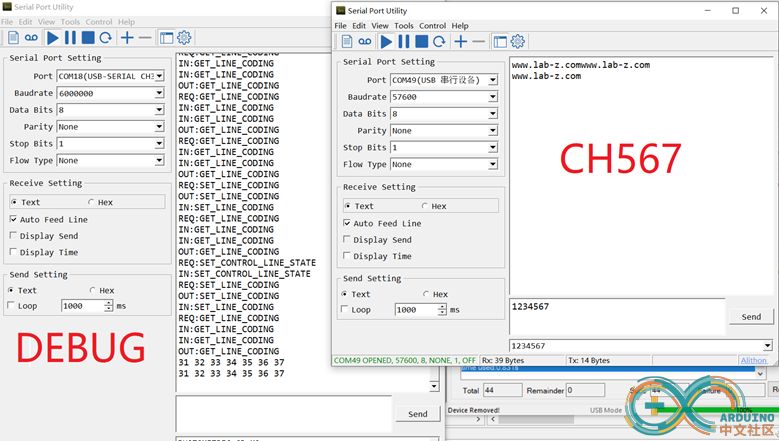
此外,还有一处需要特别注意的是:必须使用高波特率用于 printf 的串口输出(>1Mhz),实验中我使用的是 CH343 6Mhz的波特率,否则会发生丢失log的情况(实际上有跑到代码,但是对应那句话的 Log 不出现,这个问题我调试了2天,在USB 逻辑分析仪上看到了发送的数据包,但是串口 Log说没有)。 运行结果如下,左侧是用于调试的CH343产生的串口,右边是CH567模拟出来的串口。当我们对CH567发送”1234567”时,CH567收到后会从UART再次送出,因此我们在左侧能看到;此外,CH567每隔5秒发送一次” www.lab-z.com”字符串在右侧窗口可以看到。 
参考:
|