|
|
本帖最后由 topdog 于 2022-7-25 23:42 编辑

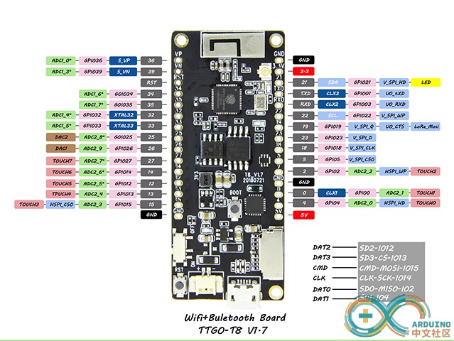
TTGO T8 1.7.1采用Espressif官方ESP32-WROVER模块制作,4MB闪存和8MB PSRAM,支持TF 内存卡。上面的图片右下角就是板载的SD卡槽走线情况。由此连线在使用TFT_eSPI库驱动2.4寸ILI9341屏幕,共用SPI总线,采用Software SPI的方法。一般爱好者会修改TFT_eSPI库中User_Setup.h的设置,但是库文件升级以后,就会被覆盖掉。
另辟蹊径,在..\Arduino\libraries\ 中创建TFT_eSPI_Setups文件夹,在里面放置你的配置文件,这样就避免了重复修改。譬如已经存入TFT_eSPI_ILI9341_TTGO_T8_user.h ,那么只需要在TFT_eSPI库的User_Setup_Select.h中,注释掉//#include <User_Setup.h>,然后添加#include <../TFT_eSPI_Setups/TFT_eSPI_ILI9341_TTGO_T8_user.h>。

在程序里引用TFT_eSPI_ILI9341_TTGO_T8_user.h 就可以了。该文件内容如下:
[pre]// ##################################################################################
//
// Section 1. Call up the right driver file and any options for it
//
// ##################################################################################
// Only define one driver, the other ones must be commented out
#define ILI9341_DRIVER // Generic driver for common displays
// For ST7735, ST7789 and ILI9341 ONLY, define the colour order IF the blue and red are swapped on your display
// Try ONE option at a time to find the correct colour order for your display
#define TFT_RGB_ORDER TFT_RGB // Colour order Red-Green-Blue
// ##################################################################################
//
// Section 2. Define the pins that are used to interface with the display here
//
// ##################################################################################
// If a backlight control signal is available then define the TFT_BL pin in Section 2
// below. The backlight will be turned ON when tft.begin() is called, but the library
// needs to know if the LEDs are ON with the pin HIGH or LOW. If the LEDs are to be
// driven with a PWM signal or turned OFF/ON then this must be handled by the user
// sketch. e.g. with digitalWrite(TFT_BL, LOW);
#define TFT_BL 22 // LED back-light control pin
#define TFT_BACKLIGHT_ON HIGH // Level to turn ON back-light (HIGH or LOW)
// For ESP32 Dev board (only tested with GC9A01 display)
// The Software SPI can be mapped to any pins
// TTGO T8 结合SD卡考虑管脚配置,SD卡CS管脚13
#define TFT_MISO 2
#define TFT_MOSI 15 // In some display driver board, it might be written as "SDA" and so on.
#define TFT_SCLK 14
#define TFT_CS 18 // Chip select control pin
#define TFT_DC 5 // Data Command control pin
#define TFT_RST 4 // Reset pin (could connect to Arduino RESET pin)
#define SD_CS 13
//#define TOUCH_CS 27 // Chip select pin (T_CS) of touch screen
// ##################################################################################
//
// Section 3. Define the fonts that are to be used here
//
// ##################################################################################
// Comment out the #defines below with // to stop that font being loaded
// The ESP8366 and ESP32 have plenty of memory so commenting out fonts is not
// normally necessary. If all fonts are loaded the extra FLASH space required is
// about 17Kbytes. To save FLASH space only enable the fonts you need!
#define LOAD_GLCD // Font 1. Original Adafruit 8 pixel font needs ~1820 bytes in FLASH
#define LOAD_FONT2 // Font 2. Small 16 pixel high font, needs ~3534 bytes in FLASH, 96 characters
#define LOAD_FONT4 // Font 4. Medium 26 pixel high font, needs ~5848 bytes in FLASH, 96 characters
#define LOAD_FONT6 // Font 6. Large 48 pixel font, needs ~2666 bytes in FLASH, only characters 1234567890:-.apm
#define LOAD_FONT7 // Font 7. 7 segment 48 pixel font, needs ~2438 bytes in FLASH, only characters 1234567890:-.
#define LOAD_FONT8 // Font 8. Large 75 pixel font needs ~3256 bytes in FLASH, only characters 1234567890:-.
//#define LOAD_FONT8N // Font 8. Alternative to Font 8 above, slightly narrower, so 3 digits fit a 160 pixel TFT
#define LOAD_GFXFF // FreeFonts. Include access to the 48 Adafruit_GFX free fonts FF1 to FF48 and custom fonts
// Comment out the #define below to stop the SPIFFS filing system and smooth font code being loaded
// this will save ~20kbytes of FLASH
#define SMOOTH_FONT
// ##################################################################################
//
// Section 4. Other options
//
// ##################################################################################
// Define the SPI clock frequency, this affects the graphics rendering speed. Too
// fast and the TFT driver will not keep up and display corruption appears.
// With an ILI9341 display 40MHz works OK, 80MHz sometimes fails
// With a ST7735 display more than 27MHz may not work (spurious pixels and lines)
// With an ILI9163 display 27 MHz works OK.
#define SPI_FREQUENCY 40000000
// Optional reduced SPI frequency for reading TFT
#define SPI_READ_FREQUENCY 60000000
// The XPT2046 requires a lower SPI clock rate of 2.5MHz so we define that here:
#define SPI_TOUCH_FREQUENCY 2500000[/pre]
其中,把SD卡的选择引脚也一并加入了,接下来就可以实现把TF卡里面的图片读取出来用2.4寸ILI9341屏幕显示出来。程序如下:
[pre]#include <SPI.h>
#include <FS.h>
#include <SD.h>
// JPEG decoder library
#include <JPEGDecoder.h>
#include <TFT_eSPI.h>
TFT_eSPI tft = TFT_eSPI(320, 240);
SPIClass SDSPI(VSPI);
//####################################################################################################
// Setup
//####################################################################################################
void setup() {
Serial.begin(115200);
SDSPI.begin(TFT_SCLK, TFT_MISO, TFT_MOSI);
digitalWrite(TFT_BL, HIGH);
tft.init();
tft.setRotation(0);
tft.begin();
if (!SD.begin(SD_CS,SDSPI)) {
Serial.println("Card Mount Failed");
return;
}
uint8_t cardType = SD.cardType();
if (cardType == CARD_NONE) {
Serial.println("No SD card attached");
return;
}
Serial.print("SD Card Type: ");
if (cardType == CARD_MMC) {
Serial.println("MMC");
} else if (cardType == CARD_SD) {
Serial.println("SDSC");
} else if (cardType == CARD_SDHC) {
Serial.println("SDHC");
} else {
Serial.println("UNKNOWN");
}
uint64_t cardSize = SD.cardSize() / (1024 * 1024);
Serial.printf("SD Card Size: %lluMB\n", cardSize);
Serial.println("initialisation done.");
}
//####################################################################################################
// Main loop
//####################################################################################################
void loop() {
tft.setRotation(3); // portrait
tft.fillScreen(TFT_BLACK);
tft.setSwapBytes(true);
// The image is 300 x 300 pixels so we do some sums to position image in the middle of the screen!
// Doing this by reading the image width and height from the jpeg info is left as an exercise!
int x = (tft.width() - 300) / 2 - 1;
int y = (tft.height() - 300) / 2 - 1;
drawSdJpeg("/EagleEye.jpg", 0, 0); // This draws a jpeg pulled off the SD Card
delay(2000);
tft.setRotation(3); // portrait
tft.fillScreen(TFT_BLACK);
drawSdJpeg("/Baboon40.jpg", 0, 0); // This draws a jpeg pulled off the SD Card
delay(2000);
tft.setRotation(3); // portrait
tft.fillScreen(TFT_BLACK);
drawSdJpeg("/lena20k.jpg", 0, 0); // This draws a jpeg pulled off the SD Card
delay(2000);
tft.setRotation(3); // portrait
tft.fillScreen(TFT_BLACK);
drawSdJpeg("/panda.jpg", 0, 0); // This draws a jpeg pulled off the SD Card
delay(2000);
tft.setRotation(2); // landscape
tft.fillScreen(TFT_BLACK);
drawSdJpeg("/Mouse480.jpg", 0, 0); // This draws a jpeg pulled off the SD Card
delay(2000);
}
//####################################################################################################
// Draw a JPEG on the TFT pulled from SD Card
//####################################################################################################
// xpos, ypos is top left corner of plotted image
void drawSdJpeg(const char *filename, int xpos, int ypos) {
// Open the named file (the Jpeg decoder library will close it)
File jpegFile = SD.open( filename, FILE_READ); // or, file handle reference for SD library
if ( !jpegFile ) {
Serial.print("ERROR: File \""); Serial.print(filename); Serial.println ("\" not found!");
return;
}
Serial.println("===========================");
Serial.print("Drawing file: "); Serial.println(filename);
Serial.println("===========================");
// Use one of the following methods to initialise the decoder:
bool decoded = JpegDec.decodeSdFile(jpegFile); // Pass the SD file handle to the decoder,
//bool decoded = JpegDec.decodeSdFile(filename); // or pass the filename (String or character array)
if (decoded) {
// print information about the image to the serial port
jpegInfo();
// render the image onto the screen at given coordinates
jpegRender(xpos, ypos);
}
else {
Serial.println("Jpeg file format not supported!");
}
}
//####################################################################################################
// Draw a JPEG on the TFT, images will be cropped on the right/bottom sides if they do not fit
//####################################################################################################
// This function assumes xpos,ypos is a valid screen coordinate. For convenience images that do not
// fit totally on the screen are cropped to the nearest MCU size and may leave right/bottom borders.
void jpegRender(int xpos, int ypos) {
//jpegInfo(); // Print information from the JPEG file (could comment this line out)
uint16_t *pImg;
uint16_t mcu_w = JpegDec.MCUWidth;
uint16_t mcu_h = JpegDec.MCUHeight;
uint32_t max_x = JpegDec.width;
uint32_t max_y = JpegDec.height;
bool swapBytes = tft.getSwapBytes();
tft.setSwapBytes(true);
// Jpeg images are draw as a set of image block (tiles) called Minimum Coding Units (MCUs)
// Typically these MCUs are 16x16 pixel blocks
// Determine the width and height of the right and bottom edge image blocks
uint32_t min_w = jpg_min(mcu_w, max_x % mcu_w);
uint32_t min_h = jpg_min(mcu_h, max_y % mcu_h);
// save the current image block size
uint32_t win_w = mcu_w;
uint32_t win_h = mcu_h;
// record the current time so we can measure how long it takes to draw an image
uint32_t drawTime = millis();
// save the coordinate of the right and bottom edges to assist image cropping
// to the screen size
max_x += xpos;
max_y += ypos;
// Fetch data from the file, decode and display
while (JpegDec.read()) { // While there is more data in the file
pImg = JpegDec.pImage ; // Decode a MCU (Minimum Coding Unit, typically a 8x8 or 16x16 pixel block)
// Calculate coordinates of top left corner of current MCU
int mcu_x = JpegDec.MCUx * mcu_w + xpos;
int mcu_y = JpegDec.MCUy * mcu_h + ypos;
// check if the image block size needs to be changed for the right edge
if (mcu_x + mcu_w <= max_x) win_w = mcu_w;
else win_w = min_w;
// check if the image block size needs to be changed for the bottom edge
if (mcu_y + mcu_h <= max_y) win_h = mcu_h;
else win_h = min_h;
// copy pixels into a contiguous block
if (win_w != mcu_w)
{
uint16_t *cImg;
int p = 0;
cImg = pImg + win_w;
for (int h = 1; h < win_h; h++)
{
p += mcu_w;
for (int w = 0; w < win_w; w++)
{
*cImg = *(pImg + w + p);
cImg++;
}
}
}
// calculate how many pixels must be drawn
uint32_t mcu_pixels = win_w * win_h;
// draw image MCU block only if it will fit on the screen
if (( mcu_x + win_w ) <= tft.width() && ( mcu_y + win_h ) <= tft.height())
tft.pushImage(mcu_x, mcu_y, win_w, win_h, pImg);
else if ( (mcu_y + win_h) >= tft.height())
JpegDec.abort(); // Image has run off bottom of screen so abort decoding
}
tft.setSwapBytes(swapBytes);
showTime(millis() - drawTime); // These lines are for sketch testing only
}
//####################################################################################################
// Print image information to the serial port (optional)
//####################################################################################################
// JpegDec.decodeFile(...) or JpegDec.decodeArray(...) must be called before this info is available!
void jpegInfo() {
// Print information extracted from the JPEG file
Serial.println("JPEG image info");
Serial.println("===============");
Serial.print("Width :");
Serial.println(JpegDec.width);
Serial.print("Height :");
Serial.println(JpegDec.height);
Serial.print("Components :");
Serial.println(JpegDec.comps);
Serial.print("MCU / row :");
Serial.println(JpegDec.MCUSPerRow);
Serial.print("MCU / col :");
Serial.println(JpegDec.MCUSPerCol);
Serial.print("Scan type :");
Serial.println(JpegDec.scanType);
Serial.print("MCU width :");
Serial.println(JpegDec.MCUWidth);
Serial.print("MCU height :");
Serial.println(JpegDec.MCUHeight);
Serial.println("===============");
Serial.println("");
}
//####################################################################################################
// Show the execution time (optional)
//####################################################################################################
// WARNING: for UNO/AVR legacy reasons printing text to the screen with the Mega might not work for
// sketch sizes greater than ~70KBytes because 16 bit address pointers are used in some libraries.
// The Due will work fine with the HX8357_Due library.
void showTime(uint32_t msTime) {
//tft.setCursor(0, 0);
//tft.setTextFont(1);
//tft.setTextSize(2);
//tft.setTextColor(TFT_WHITE, TFT_BLACK);
//tft.print(F(" JPEG drawn in "));
//tft.print(msTime);
//tft.println(F(" ms "));
Serial.print(F(" JPEG drawn in "));
Serial.print(msTime);
Serial.println(F(" ms "));
}[/pre]
如果需要用HSPI驱动就需要对配置做修改,存储的方法如前面叙述:
[pre]#define ILI9341_DRIVER // Generic driver for common displays
//色彩顺序RGB
#define TFT_RGB_ORDER TFT_RGB // Colour order Red-Green-Blue
//背光
#define TFT_BL 22 // LED back-light control pin
#define TFT_BACKLIGHT_ON HIGH // Level to turn ON back-light (HIGH or LOW)
// HSPI管脚配置
#define TFT_MISO 12
#define TFT_MOSI 13
#define TFT_SCLK 14
#define TFT_CS 15 // Chip select control pin
#define TFT_DC 5 // Data Command control pin
#define TFT_RST 4 // Reset pin (could connect to RST pin)
// 设置字体
#define LOAD_GLCD // Font 1. Original Adafruit 8 pixel font needs ~1820 bytes in FLASH
#define LOAD_FONT2 // Font 2. Small 16 pixel high font, needs ~3534 bytes in FLASH, 96 characters
#define LOAD_FONT4 // Font 4. Medium 26 pixel high font, needs ~5848 bytes in FLASH, 96 characters
#define LOAD_FONT6 // Font 6. Large 48 pixel font, needs ~2666 bytes in FLASH, only characters 1234567890:-.apm
#define LOAD_FONT7 // Font 7. 7 segment 48 pixel font, needs ~2438 bytes in FLASH, only characters 1234567890:-.
#define LOAD_FONT8 // Font 8. Large 75 pixel font needs ~3256 bytes in FLASH, only characters 1234567890:-.
#define LOAD_GFXFF // FreeFonts. Include access to the 48 Adafruit_GFX free fonts FF1 to FF48 and custom fonts
#define SMOOTH_FONT
//SPI频率
#define SPI_FREQUENCY 40000000
//否者刷屏不行
#define SPI_READ_FREQUENCY 60000000
// 使用HSPI必须选
#define USE_HSPI_PORT[/pre]
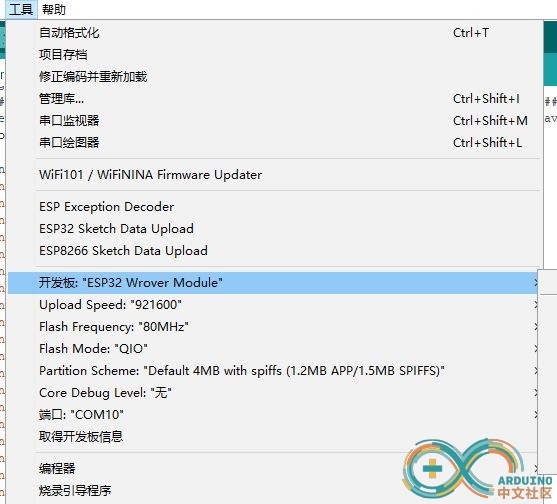
开发板要这样选择:

感兴趣的爱好者可以下载后试一试。
 data.rar
(96.74 KB, 下载次数: 2)
(全文结束)
|
|