|
|
[md]## 简介
Blinker APP中自带颜色插件,当添加颜色插件后,可以通过调整调色盘来控制实际应用中灯条对应的不同颜色。
## 器材准备
+ wifiduino主板 * 1
+ wifiduino拓展板 * 1
+ RGB灯条模块 * 2
+ 3.7V可充电电池 * 1
## 程序下载
下载程序RGBled.ino到wifiduino中
注意程序中的引脚定义及设置灯的颗数[/md]
- #define PIN D13 //连接RGB灯的引脚IO
- #define NUMPIXELS 6 //RGB灯的颗数
- #define RGB_1 “RGBKey” //app中颜色插件的键名
修改程序中的 auth[]值和要连接的wifi的ssid及密码

下载程序到wifiduino板中。下载结束后,IDE提示栏中显示“上传成功”

## 完整程序[/md]
- #define BLINKER_WIFI
- #include <Blinker.h>
- char auth[] = "Your Device Secret Key";
- char ssid[] = "Your WiFi network SSID or name";
- char pswd[] = "Your WiFi network WPA password or WEP key";
- // Download Adafruit_NeoPixel library here:
- // https://github.com/adafruit/Adafruit_NeoPixel
- #include <Adafruit_NeoPixel.h>
- #ifdef __AVR__
- #include <avr/power.h>
- #endif
- #define PIN D13
- #define NUMPIXELS 6
- Adafruit_NeoPixel pixels = Adafruit_NeoPixel(NUMPIXELS, PIN, NEO_GRB + NEO_KHZ800);
- #define RGB_1 "RGBKey"
- BlinkerRGB WS2812(RGB_1);
- void ws2812_callback(uint8_t r_value, uint8_t g_value, uint8_t b_value, uint8_t bright_value)
- {
- digitalWrite(LED_BUILTIN, !digitalRead(LED_BUILTIN));
- BLINKER_LOG("R value: ", r_value);
- BLINKER_LOG("G value: ", g_value);
- BLINKER_LOG("B value: ", b_value);
- BLINKER_LOG("Rrightness value: ", bright_value);
- pixels.setBrightness(bright_value);
- for(int i = 0; i < NUMPIXELS; i++){
- pixels.setPixelColor(i, r_value, g_value, b_value);
- }
- pixels.show();
- }
- void setup()
- {
- Serial.begin(115200);
- BLINKER_DEBUG.stream(Serial);
- pinMode(LED_BUILTIN, OUTPUT);
- digitalWrite(LED_BUILTIN, LOW);
- Blinker.begin(auth, ssid, pswd);
- pixels.begin();
- WS2812.attach(ws2812_callback);
- }
- void loop()
- {
- Blinker.run();
- }
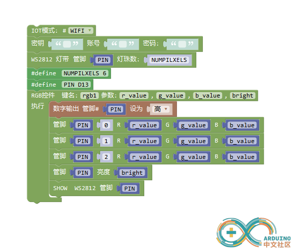
## 图形化编程程序

## blinker制定软件界面
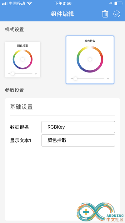
Blinker下方添加颜色插件

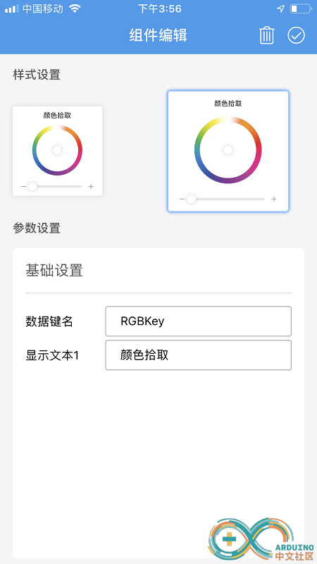
修改数据键名,键名需要与程序里定义的一致。这里我们将其取名为“RGBKey”,显示文本为“颜色拾取”

编辑好后,点击右上角的勾确认编辑结束。
## 连接硬件模块
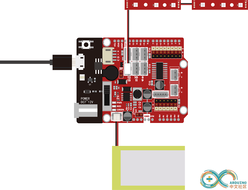
1、扩展板堆叠在wifiduino主板上
2、在程序中我们定义的是6颗RGBled,但模块上只有3课RGBled,可以将两个灯条模块进行级联。1号模块的out接口(通过3P数据线)连接在2号模块的in接口中。然后将1号模块的in接口连接在传感器扩展板上的D13接口(程序中定义)中。
3、连接完成后,插上电池,并将开关打开供电

## 观察现象
操作blinker app,通过拾取调色盘中的颜色,控制RGB灯的显示情况。[/md] |
|