草稿,还未写完
arduino-nrf24l01

测试可以通信,但非常不稳定,具体原因不详。
库下载:
 RF24.zip
(202.94 KB, 下载次数: 3279)
原地址:https://github.com/maniacbug/RF24
常用函数:
| RF24 (uint8_t _cepin, uint8_t _cspin) |
| 构造函数 | void | |
| 初始化 | void | |
| 开始监听指定的通道 | void | |
| 停止监听 | bool | write (const void *buf, uint8_t len) |
| 向指定通道发送数据 | bool | |
| 检查是否有接收到数据 | bool | read (void *buf, uint8_t len) |
| Read the payload. | void | |
| 打开数据发送通道. | void | |
| 打开数据接收通道. |
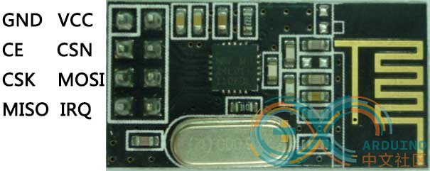
硬件连接方法:(图)
将NRF24L01的SPI引脚与Arduino的SPI引脚相连,模块CE和CSN引脚可以连接到Arduino任意引脚,模块的VCC需要连接到arduino的3.3V引脚上,在MOSI和CSK引脚和arduino引脚间,最好分别串联一个100欧电阻。
使用NRF24L01需要先包含以下头文件:[mw_shl_code=cpp,true]#include <SPI.h>
#include "nRF24L01.h"
#include "RF24.h"[/mw_shl_code]
并建立一个radio对象
[mw_shl_code=c,true]RF24 radio(9,10);[/mw_shl_code]
两个参数分别为Arduino连接CE和CSN的引脚
发送端:
[mw_shl_code=cpp,true]
/*
*/
#include <SPI.h>
#include "nRF24L01.h"
#include "RF24.h"
RF24 radio(9,10);
const uint64_t pipe = 0xE8E8F0F0E1LL;
void setup(void){
Serial.begin(57600);
radio.begin();
radio.openWritingPipe(pipe);
radio.printDetails();
pinMode(2,INPUT_PULLUP);
}
char command[6]="hello";
void loop(void)
{
uint8_t state = ! digitalRead(2);
if (digitalRead(2)==LOW){
Serial.print("Sending...");
bool ok = radio.write(command,5);
if(ok)
Serial.println("successed");
else
Serial.println("failed");
}
delay(500);
}
[/mw_shl_code]
接收端:
[mw_shl_code=cpp,true]
#include <SPI.h>
#include "nRF24L01.h"
#include "RF24.h"
RF24 radio(9,10);
const uint64_t pipe = 0xE8E8F0F0E1LL;
void setup(void){
Serial.begin(57600);
radio.begin();
radio.openReadingPipe(1,pipe);
radio.startListening();
radio.printDetails();
}
void loop(void){
char command[6];
if (radio.available()){
radio.read( command, 5 ); Serial.println(command[0]);
delay(500);
}
}
[/mw_shl_code]
通常以上程序就可以完成简单的点对点传输了,当然,RF24库还提供了其他可选配置:
void | |
| Set the number and delay of retries upon failed submit. | void | |
| Set RF communication channel. | void | |
| Set Static Payload Size. | uint8_t | |
| Get Static Payload Size. | uint8_t | |
| Get Dynamic Payload Size. | void | |
| Enable custom payloads on the acknowledge packets. | void | |
| Enable dynamically-sized payloads. | bool | |
| Determine whether the hardware is an nRF24L01+ or not. | void | |
| Enable or disable auto-acknowlede packets. | void | |
| Enable or disable auto-acknowlede packets on a per pipeline basis. | void | |
| Set Power Amplifier (PA) level to one of four levels. | | |
| Fetches the current PA level. | bool | |
| Set the transmission data rate. | | |
| Fetches the transmission data rate. | void | |
| Set the CRC length. | | |
| Get the CRC length. | void | |
| Disable CRC validation. |
|