|
|
本帖最后由 零知实验室-roc 于 2019-1-11 17:26 编辑
零知增强板-WIFI网络图像传输 OV2460 ESP8266 SPI传输
http://www.lingzhilab.com/forum. ... d&tid=909&fromuid=2
(出处: 零知实验室)
本次实验主要使用零知增强板+ESP8266无线模块+OV2640,将摄像头数据通过WIFI传输到上位机进行显示,程序有很多地方需要优化,这里仅仅抛砖引玉,提供一个网络传输图像的大体思路。
1、硬件连接
ESP8266与零知增强板连接如下:(参照之前ESP8266 SPI方式传输文章)

零知增强板与OV2640/OV7670摄像头连接:
零知增强板上自带摄像头接口,请直接接入摄像头模块,这里使用的是OV2640摄像头进行试验。
2、软件代码编写
(1)零知平台代码,本次实验使用UDP进行传输,零知板上的ESP8266作为UDP客户端与上位机进行通信,主要代码如下:
[mw_shl_code=arduino,true]/*WiFiSPI example: esp8266连接AP,UDP传输数据
电路连接:
1. On ESP8266 must be running (flashed) WiFiSPIESP application.
2. Connect the Arduino to the following pins on the esp8266:
ESP8266 |
GPIO NodeMCU Name | Lingzhi Enhanced Board
===================================
15 D8 SS | 53
13 D7 MOSI | 51
12 D6 MISO | 50
14 D5 SCK | 52
*/
#include "WiFiSpi.h"
#include "WiFiSpiUdp.h"
#include "camera.h"
#include <fsmc_lcd.h>
CAMERA_DCMI_INTERFACE camera;
#ifdef JPEG_OUTPUT_MODE
uint32_t jpeg_buf[jpeg_buf_size]; //JPEG数据缓存buf
extern volatile uint8_t jpeg_data_ok;
extern volatile uint32_t jpeg_data_len;
#endif
unsigned int localPort = 8081;
#define ssid "lingzhilab"//换成自己的wifi热点
#define password "lingzhilab.com"
char udpServerIP[] = "192.168.0.126";
int serverPort = 8081;
#define PACKET_SIZE 512
byte packetBuffer[PACKET_SIZE];
const int UDP_TIMEOUT = 2000;
WiFiSpiUdp udpClient;
WiFiSpiClient client;
uint8_t connect_server_flag = 0;
void setup()
{
// initialize serial for debugging
Serial.begin(9600);
Serial3.begin(460800);//camera data
// initialize the ESP module
WiFiSpi.init();
// 检查是否连接了运行SPIWifi程序的8266模块
if (WiFiSpi.status() == WL_NO_SHIELD) {
Serial.println("WiFi shield not present");
// don't continue
while (true);
}
int status = WL_IDLE_STATUS;
// attempt to connect to WiFi network
while (status != WL_CONNECTED) {
Serial.print("Attempting to connect to WPA SSID: ");
Serial.println(ssid);
// Connect to WPA/WPA2 network
status = WiFiSpi.begin(ssid, password);
}
// you're connected now, so print out the data
Serial.println("You're connected to the network");
udpClient.begin(localPort);
//camera begin
camera.begin(OV2640_DEVICE_ID);
#ifdef JPEG_OUTPUT_MODE
camera.setOutSize(800,600);
camera.startCapture((uint32_t)&jpeg_buf);
#endif
}
void loop()
{
sendPacket(udpServerIP); // send an packet to server
// wait ten seconds before asking for the time again
//delay(100);
}
int i;
uint8_t *p;
// send an packet to server
void sendPacket(char *server)
{
//send camera data process
{
if(jpeg_data_ok==1) //
{
p=(uint8_t*)jpeg_buf;
// Serial.println("send one frame data...");
int times = jpeg_data_len*4/1024;
int retlen = jpeg_data_len*4 - 1024*times;
int x = 0;
for(x=0; x<times; x++)
{
udpClient.beginPacket(server, serverPort);
udpClient.write(p+1024*x,1024);
udpClient.endPacket();
}
udpClient.beginPacket(server, serverPort);
udpClient.write(p+1024*x,retlen);
udpClient.endPacket();
jpeg_data_ok=2; //
}
}
}[/mw_shl_code]
上述代码中,需要替换自己的WIFI热点名字和密码。
(2)上位机代码编写:
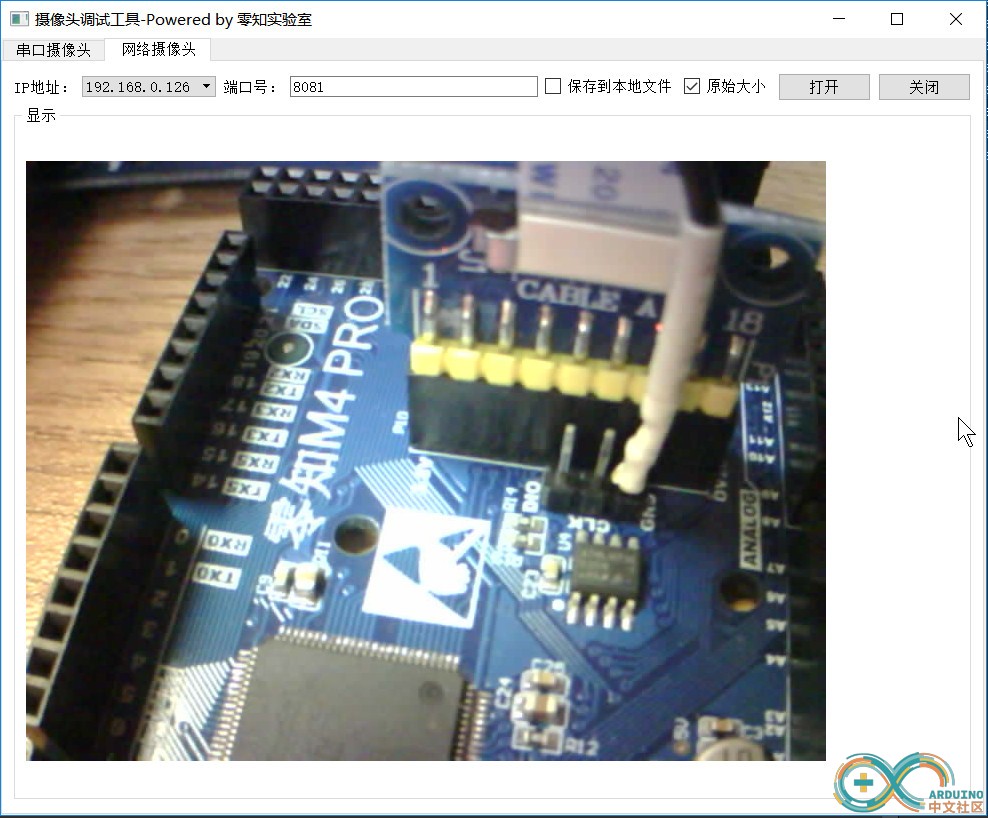
参考这里,源码开放下载,根据自己需求进行更改即可:OV2640网络摄像头上位机+串口摄像头 调试工具源码。
3、测试验证
将模块按照步骤1正确连线后,将代码验证后上传到零知平台,然后就可以在上位机通过WIFI查看摄像头数据了,这里仅传输JPG格式图像,数据量较少,有时候会出现图像不完整的情况,因此需要一定的优化已达到更好的效果。

附件:完整工程和库请到原文下载。
上位机源码请到:OV2640网络摄像头上位机+串口摄像头 调试工具源码 这里下载。
|
|