本帖最后由 老殷 于 2017-7-9 12:41 编辑
ARDUINO 101自带陀镙仪和加速器,所以它可以用于需要平衡的设备上
实验所需:
硬件:
ARDUINO 101开发板
软件:ARDUNIO IDE
processing
连接:只需要将ARDUINO 101连接到电脑即可,用IDE编译以下代码,实现平衡参数从串口输出,通过processing这个画数据画图软件来接收串口数据,画出板子的平衡状态,processing的代码在后面贴出。
以下为ARDUINO IDE 的代码 CurieIMU.h,MadgwickAHRS.h文件下载地址
 CurieIMU.rar
(42.52 KB, 下载次数: 6)
 Madgwick.rar
(6.59 KB, 下载次数: 3)
用法:老鸟不要看,新手:将文件解压后复制到ARDUINO IDE程序目录下的libraries文件夹下,即可#include <CurieIMU.h>
#include <MadgwickAHRS.h>
Madgwick filter;
unsigned long microsPerReading, microsPrevious;
float accelScale, gyroScale;
void setup() {
Serial.begin(9600);
// 启动惯性测量单元和滤波器
CurieIMU.begin();
CurieIMU.setGyroRate(25);
CurieIMU.setAccelerometerRate(25);
filter.begin(25);
// 将加速度计范围设置为2G
CurieIMU.setAccelerometerRange(2);
// 将陀螺仪量程设置为250度/秒。
CurieIMU.setGyroRange(250);
// 初始化变量以更新正确率
microsPerReading = 1000000 / 25;
microsPrevious = micros();
pinMode(2,OUTPUT);
pinMode(3,OUTPUT);
}
void loop() {
int aix, aiy, aiz;
int gix, giy, giz;
float ax, ay, az;
float gx, gy, gz;
float roll, pitch, heading;
unsigned long microsNow;
// 检查是否读取数据并更新筛选器
microsNow = micros();
if (microsNow - microsPrevious >= microsPerReading) {
// 从curieimu读取原始数据
CurieIMU.readMotionSensor(aix, aiy, aiz, gix, giy, giz);
// 从原始数据转换为重力和度/秒单位
ax = convertRawAcceleration(aix);
ay = convertRawAcceleration(aiy);
az = convertRawAcceleration(aiz);
gx = convertRawGyro(gix);
gy = convertRawGyro(giy);
gz = convertRawGyro(giz);
// 更新计算方向的筛选器
filter.updateIMU(gx, gy, gz, ax, ay, az);
if(filter.getPitch()<=0)
{digitalWrite(2,HIGH);}
else{digitalWrite(2,LOW);}
if(filter.getRoll()<=0)
{digitalWrite(3,HIGH);}
else{digitalWrite(3,LOW);}
// 打印标题、音高和滚动
roll = filter.getRoll();
pitch = filter.getPitch();
heading = filter.getYaw();
Serial.print("Orientation: ");
Serial.print(heading);
Serial.print(" ");
Serial.print(pitch);
Serial.print(" ");
Serial.println(roll);
// 增加以前的时间,所以我们要保持适当的步伐。
microsPrevious = microsPrevious + microsPerReading;
}
}
float convertRawAcceleration(int aRaw) {
/*因为我们使用2G范围
2G映射到原始值为32768
2G映射到原始值为32767
*/
float a = (aRaw * 2.0) / 32768.0;
return a;
}
float convertRawGyro(int gRaw) {
/*因为我们使用250度/秒范围
- 250到原始值为32768的映射
+ 250映射到原始值为32767
*/
float g = (gRaw * 250.0) / 32768.0;
return g;
}
以下为processing的代码,根据你自己的串口,你可能会更改串号和波特率和你的开发板相对应,processing还可以编译成一个.exe的可执行程序,这样,你的设备平衡状态只需要打开这个编译好的程序就可以看到设备的平衡状态,这个对于想要开发平衡设备的朋友来说应该是相当不错的。
import processing.serial.*;
Serial myPort;
float yaw = 0.0;
float pitch = 0.0;
float roll = 0.0;
void setup()
{
size(600, 500, P3D);
// if you have only ONE serial port active
//myPort = new Serial(this, Serial.list()[0], 9600); // if you have only ONE serial port active
// if you know the serial port name
myPort = new Serial(this, "COM2", 9600); // Windows
//myPort = new Serial(this, "/dev/ttyACM0", 9600); // Linux
//myPort = new Serial(this, "/dev/cu.usbmodem1217321", 9600); // Mac
textSize(16); // set text size
textMode(SHAPE); // set text mode to shape
}
void draw()
{
serialEvent(); // read and parse incoming serial message
background(255); // set background to white
lights();
translate(width/2, height/2); // set position to centre
pushMatrix(); // begin object
float c1 = cos(radians(roll));
float s1 = sin(radians(roll));
float c2 = cos(radians(pitch));
float s2 = sin(radians(pitch));
float c3 = cos(radians(yaw));
float s3 = sin(radians(yaw));
applyMatrix( c2*c3, s1*s3+c1*c3*s2, c3*s1*s2-c1*s3, 0,
-s2, c1*c2, c2*s1, 0,
c2*s3, c1*s2*s3-c3*s1, c1*c3+s1*s2*s3, 0,
0, 0, 0, 1);
drawArduino();
popMatrix(); // end of object
// Print values to console
print(roll);
print("\t");
print(pitch);
print("\t");
print(yaw);
println();
}
void serialEvent()
{
int newLine = 13; // new line character in ASCII
String message;
do {
message = myPort.readStringUntil(newLine); // read from port until new line
if (message != null) {
String[] list = split(trim(message), " ");
if (list.length >= 4 && list[0].equals("Orientation:")) {
yaw = float(list[1]); // convert to float yaw
pitch = float(list[2]); // convert to float pitch
roll = float(list[3]); // convert to float roll
}
}
} while (message != null);
}
void drawArduino()
{
/* function contains shape(s) that are rotated with the IMU */
stroke(0, 90, 90); // set outline colour to darker teal
fill(0, 130, 130); // set fill colour to lighter teal
box(300, 10, 200); // draw Arduino board base shape
stroke(0); // set outline colour to black
fill(80); // set fill colour to dark grey
translate(60, -10, 90); // set position to edge of Arduino box
box(170, 20, 10); // draw pin header as box
translate(-20, 0, -180); // set position to other edge of Arduino box
box(210, 20, 10); // draw other pin header as box
}
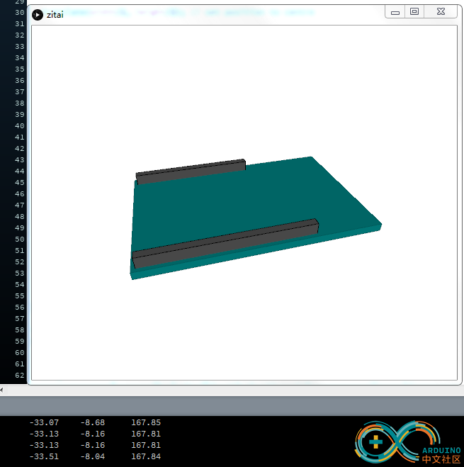
效果如下:

根据这个可以实时地从画面上看到你的设备平衡状态,当然,你也可以改写一下IDE的代码,加个判断什么的,比如X,Y,Z三轴的数值没有在平衡点的时候采取什么样一个措施,再比如processing的代码,更改一下画出的图形,改成一个飞机,一个小车,希望我这个混分的文章能给你带来一点点启发。
|